Hardware Button
in the Raspberry Pi
Posted
by
Jeena
![]()
I am working on a remote door phone which I'd like to use via the Internet. The goal is to have a Raspberry Pi hooked up to the Internet and letting people press a button which will then start a SIP call over the internet. It will either ring on my computer when I am online, or call my phone so I can answer it.
There are a couple of console SIP clients. I am using linphonec. I installed it and configured it with its own SIP account and tested that it could call my SIP client at home. After a couple of days of trial and error it finally worked.
Next step was to attach a hardware button to the Raspberry Pi and to listen to it when it was pressed, so I could set up the call. This proved much more complicated than I expected.
The problem was not so much that you have to do much, the problem was rather that all the documentation around it assumed you're comfortable with all the abbreviations and the electronics side of the whole thing. Neither was the case here.
First I tried to implement a simple blinking light, like it is for example described in: Wiring Pi - Blink. The first and biggest problem was that the example uses its own numbering system of the pins. In the image it hooks up the wires to pin 6 and 11 but in the code it only writes to pin 0. I couldn't figure it out so I had to ask on the IRC which led to quite a lot of confusion.
I confused four different numbering systems, first I thought that the label P1 on the Raspberry Pi means that this is pin 1, but it does not, it means header one, which holds all the pins you as a user are supposed to use. There is P2 too for some other stuff.
Second I thought that pin 0 is the top left most pin. That is not the case, pin 0 which is defined by the Wiring Pi software's own numbering is actually the physical pin number 11. There is a PDF describing it which I didn't understand.
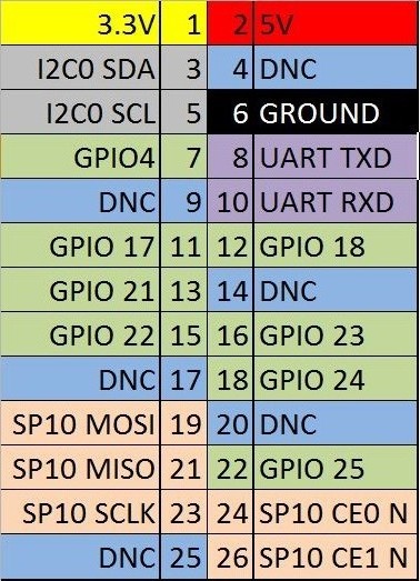
Then finally I went on to look on YouTube for better explanations and found tons of videos which still didn't explain which pin number means what. I found a video where someone wires the blink example and then goes on to say that he is hooking up the GPIO 18 which has the physical pin 12. Only then I did understand the fourth numbering system and was finally able to read images like this:
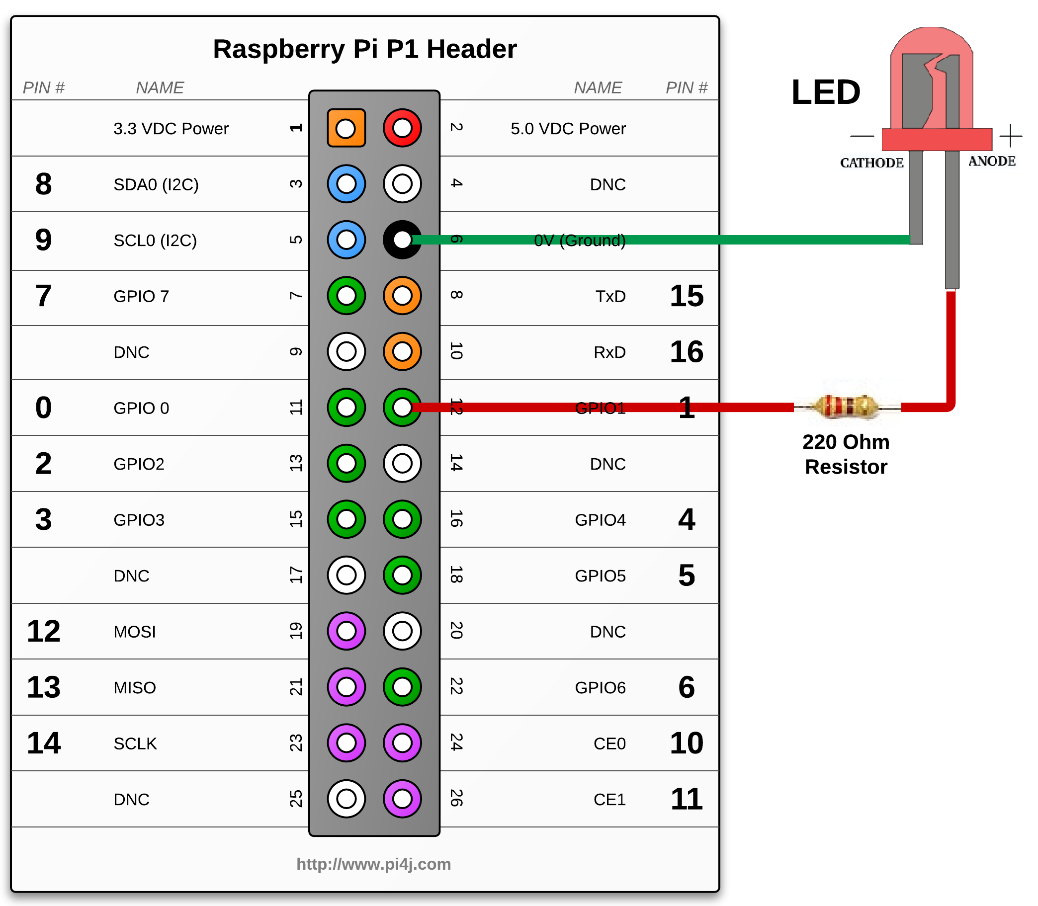
Or actually this is the right one:
Do you see how confusing this all is? I don't understand why there are that many numbering systems for one devise.
Ok, very nice, I hooked up the LED with the only resistor type I have from another project with the Arduino, then I compiled and installed the gpio console client from the Wiring Pi website with which I am supposed to be able to set pins to high and low, so the LED would go on and off.
Sadly nothing happened, and it took me another couple of hours to finally watch a video where they explicitly tell you that you need to wire up the cathode, the shorter leg of the LED, to ground, because otherwise it would not work. Looking at the image above I now see that it has been there all along. But if you don't know that, it isn't very obvious, especially if you still struggle with all the pin numbering systems.
After I got that I was able to use different libraries, from C over python to ruby to get my LED to blink. But I decided that it is a waste of resources and I would implement it by foot as a bash script.
Now that I understood the pin numbering and found a video which showed how to wire the button it was actually easier to work directly with the virtual file system which works really nice with a shell script, than with all the libraries which do the same but come up with their own numbering systems which makes it so confusing.
Anyway, here is my script which is working nice even if I don't quite understand why it is telling me that the button is 0 if it is pressed and 1 if it is not in line 12.
   01 #!/bin/sh
   02
   03 BUTTON_GPIO=22
   04 BUTTON=/sys/class/gpio/gpio$BUTTON_GPIO
   05 RELEASED=1
   06
   07 echo $BUTTON_GPIO > /sys/class/gpio/export
   08 echo "in" > $BUTTON/direction
   09
   10 while [ 1 ]
   11 do
   12       if [ `cat $BUTTON/value` -eq 0 ]
   13       then
   14                if [ $RELEASED -eq 1 ]
   15                then
   16                        RELEASED=0
   17
   18                        echo "Button pressed"
   19                fi
   20       else
   21                RELEASED=1
   22       fi
   23 done
It is quite cool and easy to understand. I had to add the RELEASED variable because it otherwise would fire up the call in line 18 all the time while the person is pressing, which is a couple of ten times a second.
I hope this blog post can help someone in the future to be less confused about all the numbering systems than I was.
6 Replies
Man, write that in python.
Na python is bloat! Bash is for real man :-p
No man, when it comes to hardware, C is for a real man.
Or, this: https://www.npmjs.org/package/pi-gpio
The event-driven nature of javascript makes the language a perfect candidate for this kind of stuff in my opinion. Well,maybe not if the hardware to control is very complicated and if in case of failure people will be affected.
Yeah I was thinking about C but the only thing that this script has to do is to call another shell program when the button is pressed, so this was the easiest way out, without compiling and installing anything, just working on the bare virtual file system. And running a whole JavaScript virtual machine just to check if the button was pressed is kind of shooting in your own foot ;). I don’t want to waste too much energy because I might run the whole thing of a battery which will be charged with solar power. So the standby energy consumption should be as low as possible. So yeah C perhaps would be the best way to go here.
2 Mentions
GPIO w Raspberry Pi Typ B - Poradnik informatyka
domotica a soli € 100.22 – Euroinfissi Sabellico
1 Like